
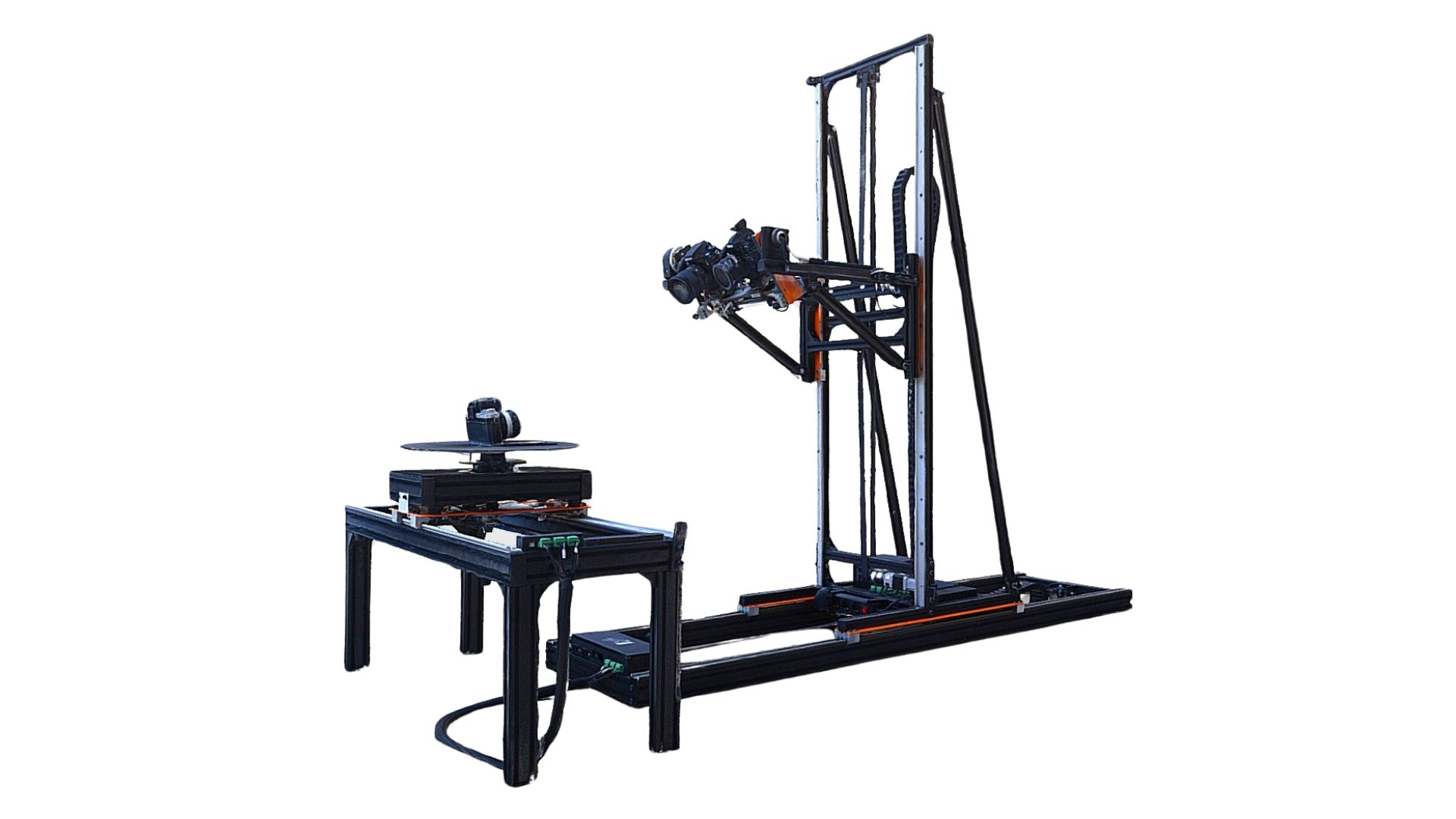
What is the Arago Rigster?
The Arago Rigster is great for capturing both big and small objects. The Rigster requires booking and can only be used during staffed hours in uCreate. There is no training for the use of this equipment. Please consult staff the first time you are using the equipment.
Key Features:
- Lighting equipment to help light your subject.
- 5-axis design driven by high-quality stepper motors provides precise and fast motion.
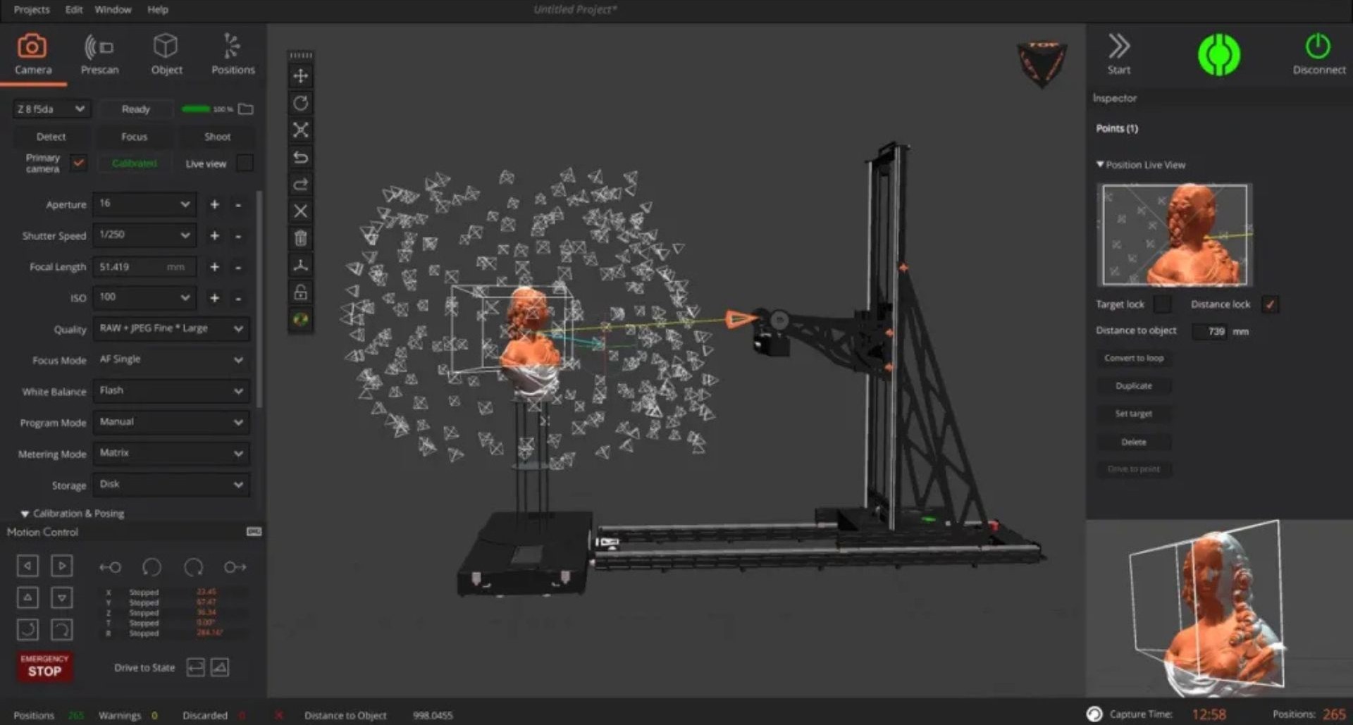
- Dedicated software Arago Control generates an optimal distribution of image-capture positions for your object.
- Adjustable motor speed control helps with refined motion of more delicate objects.
Recommended Use: Photorealistic accuracy. Capturing a subject with lots of colour or visual detail data.
What could I use the Arago Rigster for?
- Automating capturing detailed, 360-degree images of your subject to turn into interactive photos or 3D scans.
- Capturing subjects with lots of colour and visual data that depend upon accuracy.
- Capture objects with volume varying between 5 – 180 cm depending on the configuration of the turntable module and camera field of view.
- 360-degree Turntable with a side-to-side motion and a payload of 80 KG. It comes with 30 – 60 cm extension modules for additional object elevation and flexible mounting options.
- Detachable turntable module enables capture of larger objects and ensures absolute safety.
- Camera tilting component provides additional reach around the scanning area and can accommodate up to 10kg of equipment.

Health and Safety.
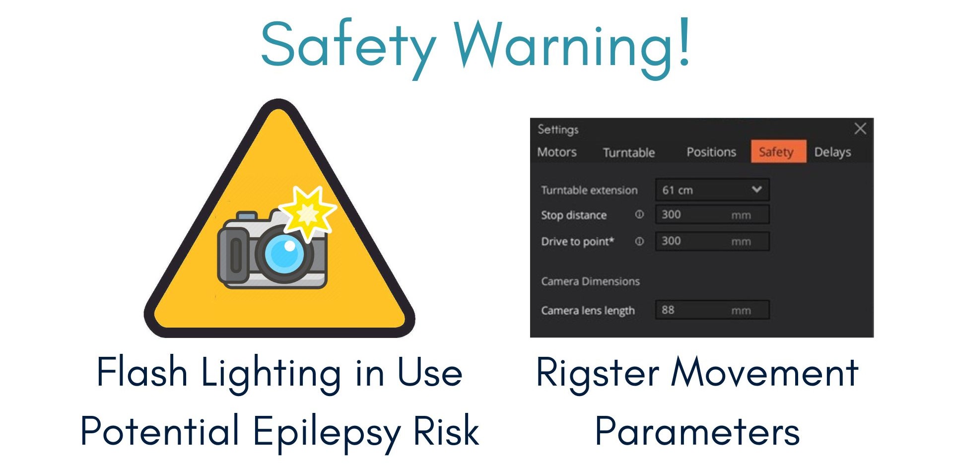
The camera attached to the Rigster has a large flash which will (usually) be turned on during image capture.
Aside from this, when setting up the rig, there are safety settings to ensure that the rig does not crash into the object it is capturing, causing damage.
You must always catch the rig while it initilizes and first starts capturing photos.
The settings in the Safety tab should be the following:
- Turntable extension: 61cm (unless using the lower height)
- Stop distance: 300mm
- Drive to point: 300mm
- Camera lens length: 88mm (for the standard 50mm lens)
See the workflow below for more details.
How do I access the Arago Rigster?
To use the Arago Rigster, you will first need to be an inducted member of uCreate. If you have not yet been inducted, you can book an induction here.
If you have never worked with photogrammetry before, we recommend reading the Introduction to Photogrammetry on the Knowledge Base or speaking to a member of staff who can assist you. Our equipment comes with a step-by-step manual sheet to walk you through the process from start to finish.
To book the Arago Rigster, please visit the Equipment Bookings page.

Arago Rigster Workflow.
The following workflow details how to capture images for photogrammetry using the Arago Rigster.
Turning on the Rigster.
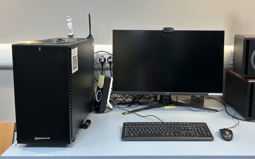
1. Log into the photogrammetry PC.
Username: General User
This account uses the standard uCreate user password.
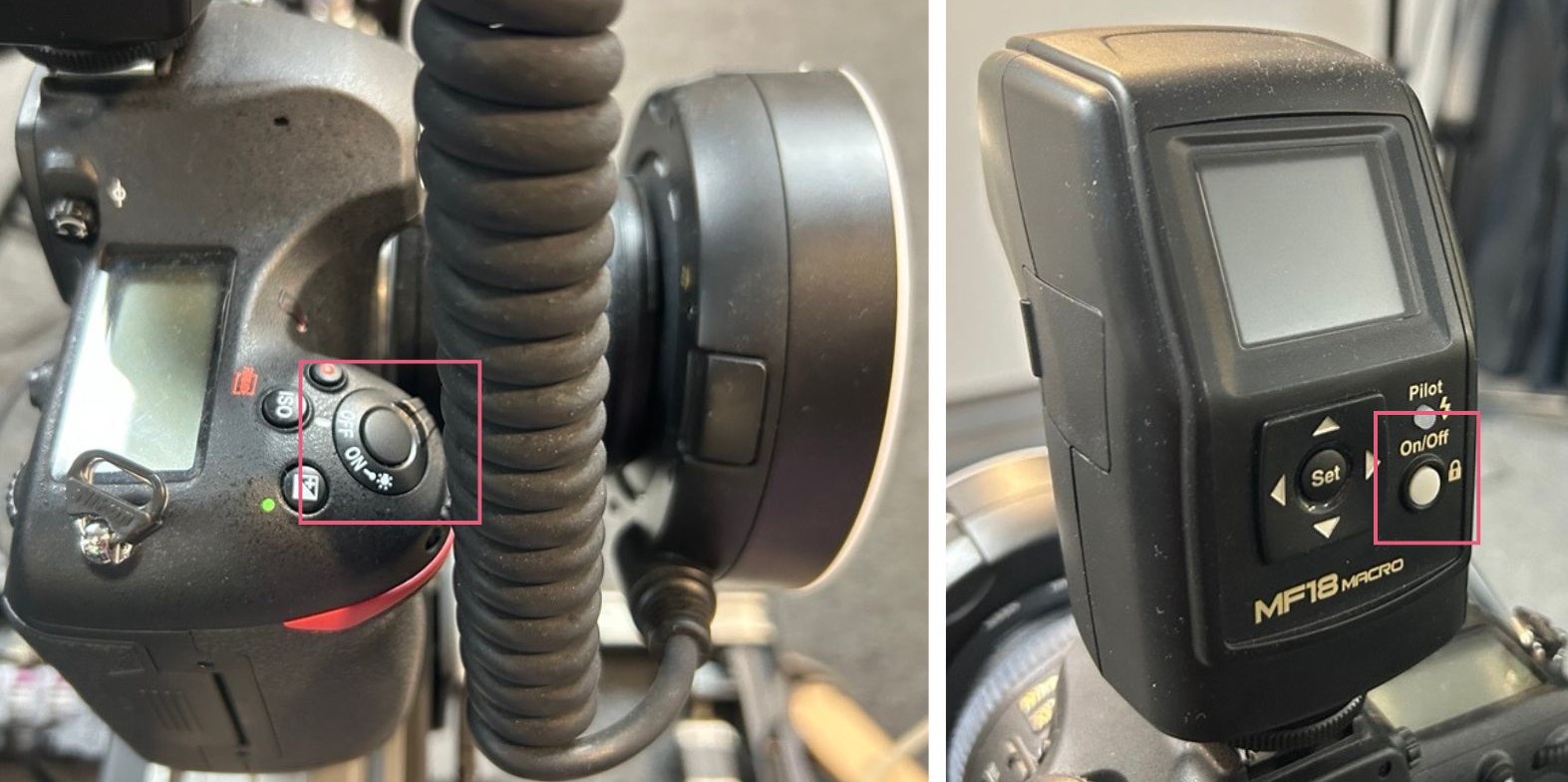
2. Turn on the camera and it's flash, checking they have full battery.
There are 4 camera batteries, always make sure another one is charged so you can swap when needed.
Do not remove the camera to change the battery. This can alter the calibration.
The flash pack is fully charged when the pilot light is green.
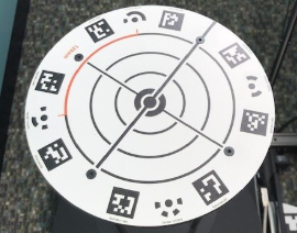
3. Ensure the tall turntable plate (with targets) is installed.
The target plate should be installed over the baseplate with the countersunk screws in the baseplate.
If you require the turntable plate changing, speak to a member of uCreate staff.
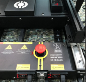
4. Turn on the Rigster using the left-hand power switch (1) at the back of the Rigster.
The right-hand switch (2) is for the additional power points at the back of the rig (4). The emergency off switch is the large red button (3).
Setting up your object and project folder.
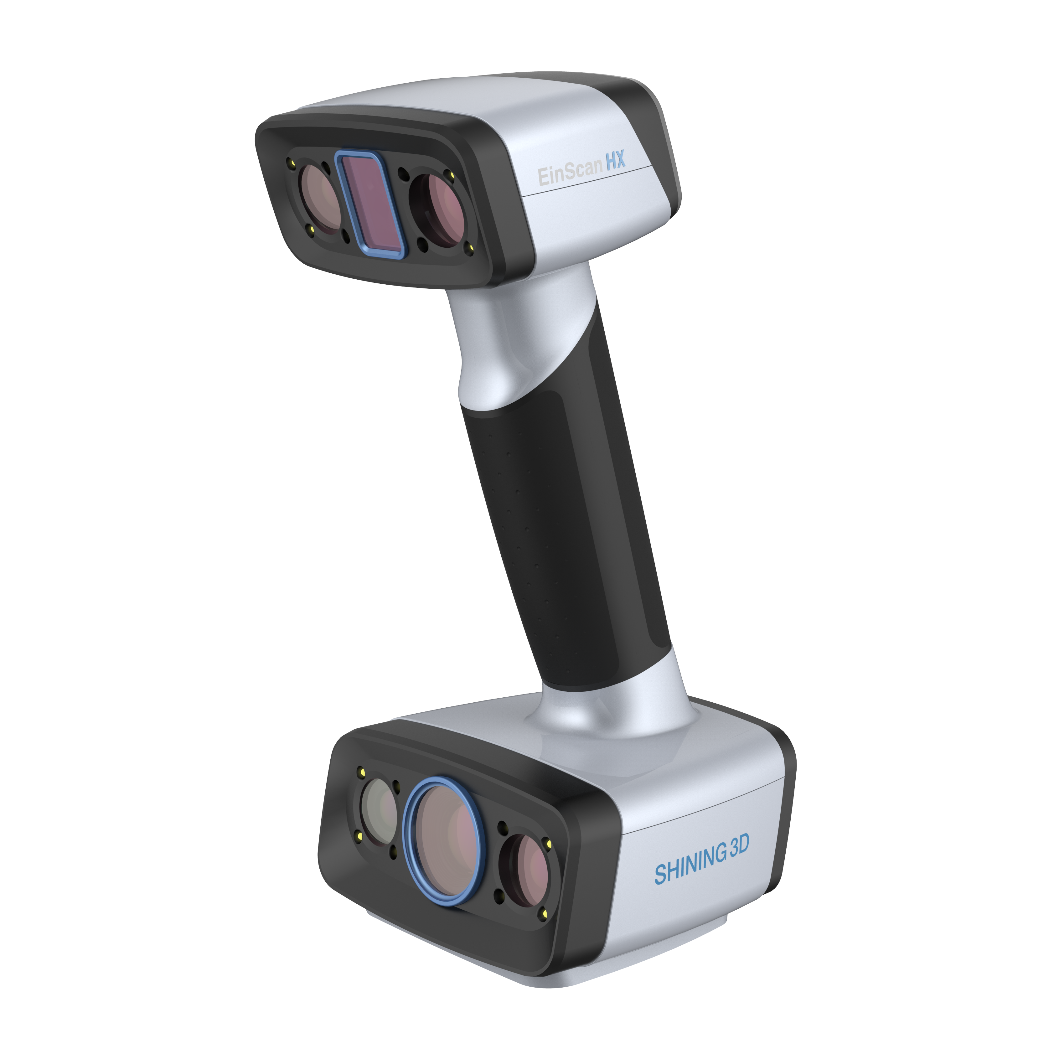
5. Use the EinScan HX to generate a rough 3D model for your object.
The easiest way to later tell the Arago Rigster where your object is for photographing, is to drop in a 3D scan on the model. A scan is fast to complete using the EinScan HX. For more information, see the EinScan HX knowledge base page.
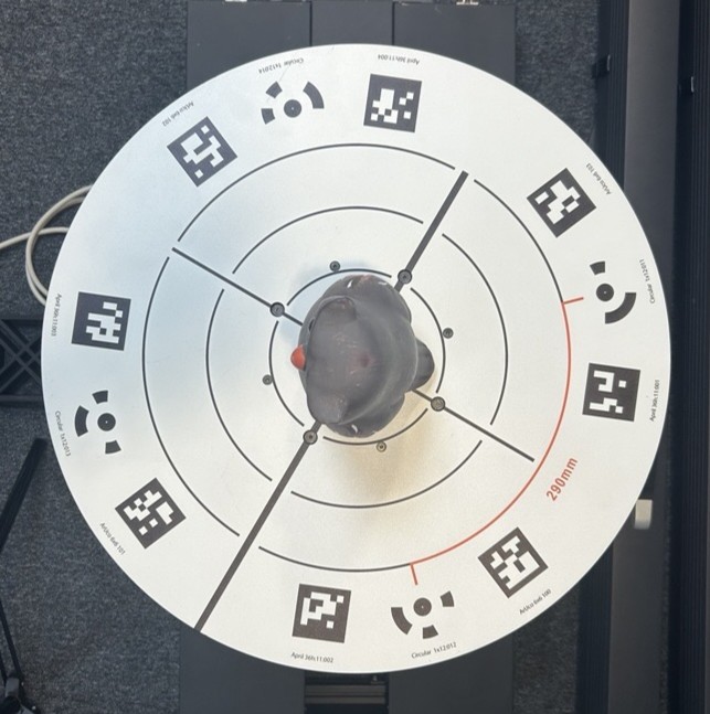
6. Place your object as centrally as possible on the turntable plate.
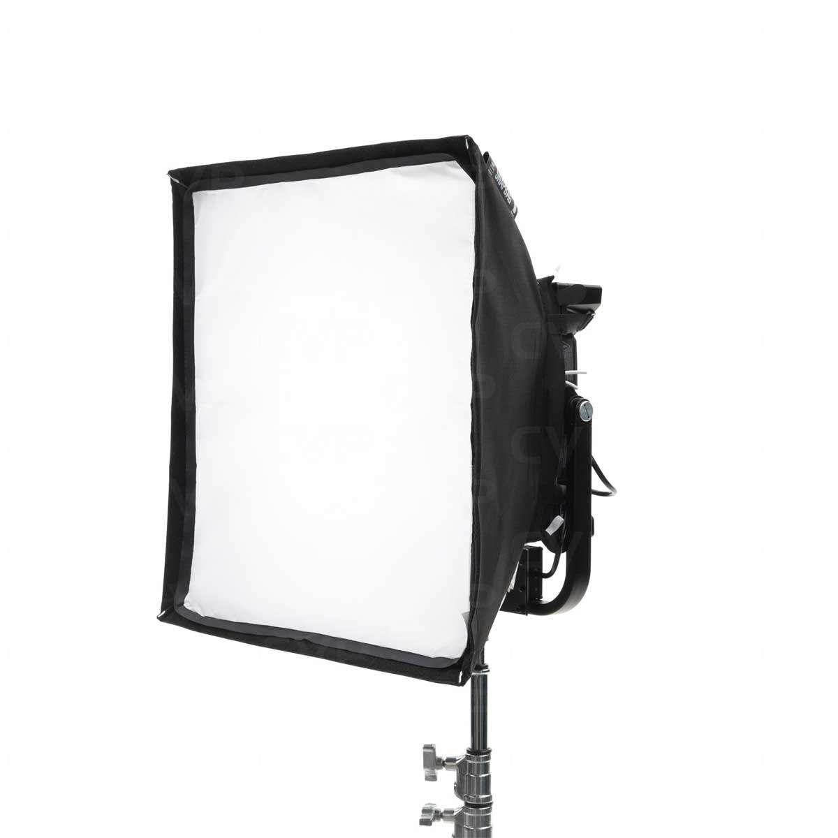
7. Use the free standing light panels to light your object.
Lighter objects will require less lighting than darker object. Reflectors or the flash ring around the camera lens can be used to counteract shadows.
Without the lighting panels the greenscreen may reflect a green tint against the white panel background – this will affect your colour data if not adjusted.
If you require moving or changing the height of the lights, speak to a member of uCreate staff for assistance.
8. Open the Arago application and click the + button in the top right corner of the Welcome to Arago control menu to open a new project.
Name your file with identifiable information – for example your UUN/staff name or your unique project title.
Connecting to Arago Rigster.

9. Click the connect button found in the orange box on the right side of the screen to connect to the camera.
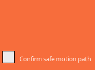
10. Ensure the tracks are clear and tick the Confirm Safe Motion Path box found under the button titled Initialize.

11. Click the Initialize button to begin initializing.
The rig will begin moving during initilization. Watch the rig during the initilization process.
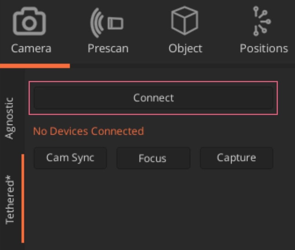
12. Click the 'Tethered' tab on the left side under the camera menu. Click 'connect' to connect to the DSLR that is already attached to the rig.
Once the camera is connected, the camera settings menu will appear.
Scroll down through the camera settings and click Live View to open a small point-of-view window of what the camera sees.
Setting up the tethered camera.

13. Use the motion control buttons to centre the camera on the Pose Camera calibration target at the base of the turntable.
Use the Primary Camera Focus button if necessary (not the focus button up in between Cam Sync and Capture – the Focus button is found underneath the Primary Camera box).
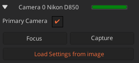
14. Click the Primary Camera 'Capture' button to capture an image of the Pose Camera calibration target.

15. After capturing your image, click the Load Settings from Image button and select your image from the appropriate file (whether JPEG Fine or TIFF).
Once uploaded, Arago will automatically input the camera's information.
Calibration, Posing and Tethering Controls.
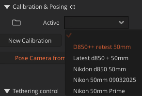
16. Click on the drop down box next 'Active' and select D850++ retest.
The calibration for the DSLR will be automatically activated.
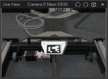
17. Click on the cube shape at the top right of the Live View bar to overlay the photo with the actual live view. This allows you to see how well calibrated the camera position is.
Recalibration is necessary if the overlay of the image you captured for primary focus does not align with the live view of the camera, but it does not need to be perfect. It needs to be accurate enough, so the rig knows where camera exists relative to the object and the plate.
If further calibration is required, speak to a member of uCreate staff. Further calibration instructions can be found here: https://rigsters.com/arago/docs/camera-calibration-and-posing/
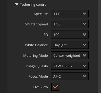
18. Ensure the tethering controls match the below.
- Aperture: f11 or f16.
- Shutter Speed: 1/60th or above.
- ISO: lower is preferred for the best quality, 100 is recommended.
- White balance: Daylight.
- Metering mode: centre weighted.
- Image Quality: select RAW + JPG Fine (could select TIFF depending on preference).
- Focus mode: AF-C.
Checking the safety controls.

19. Click on Window and then Settings.

20. In Settings the Motor tab allows you to choose the speed at which the table rotates.
For delicate objects, select slow or mid-speed.
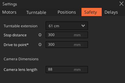
21. In the Settings, Safety tab, the parameters should be set to the following values.
- Turntable extension: 61cm (unless using the lower height)
- Stop distance: 300mm
- Drive to point: 300mm
- Camera lens length: 88mm (for the standard 50mm lens)
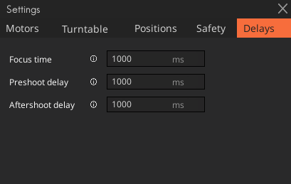
22. Check the settings in the Delays tab are set to 1000ms.
You can change the settings here to allow time for auto-focus to finish before each capture. You can also allow time for objects to settle with the pre-shoot delay; this is useful when there may be some movement on the object.
Setting camera positions using imported 3D scan and loops.
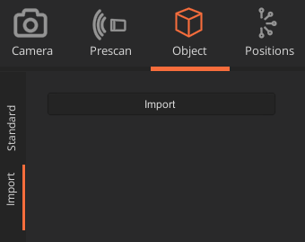
23. Click import to import an STL file of your object, previously captured using the EinScan HX.
This gives the rig a good idea of what the ratio and object structure are like.
Book the 3D Scanning station ahead of time to capture a scanned model of your object, no texture data is needed.
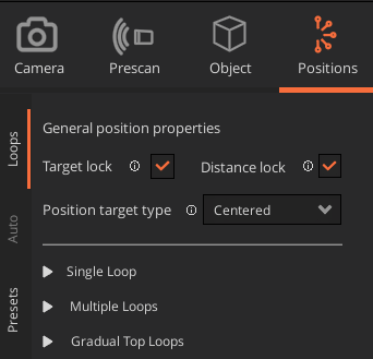
24. Go to the Positions tab and select Loops.

25. Under Multiple loops, set your number of loop, how many images per loop and the distance from the object the camera should be. Click Generate and the camera positions will then be shown in the workspace area.
The distance will need to be set at least as high as the safety setting.
Adjusting your set loops.
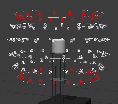
26. If there are any camera positions that have an obscured view, or are at an unsafe distance, they will show as red.
To fix this, either delete or edit the loops.
Clicking the red x at the bottom left of the screen will remove all the red camera points.
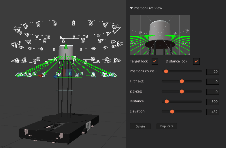
27. Click on a loop to select it, you will see you now have additional controls in the Inspector panel on the right. Here you can adjust the loop:
- Target lock: by unchecking the target lock, you can then use the move tools to alter the up/down & side to side location of the Cameral Positions.
- Distance lock: by unchecking the distance lock, you can then use the move tools to alter the in/out & side to side location of the Cameral Positions.
- Zig-zag: makes every other shot go to a slightly different height to create a parallax between the images on the loop, which can benefit the model creation.
- Positions count: increase or decrease the number of shots/loops.
- Tilt Avg: to change the tilt, you also need to unlock the Target Lock.
- Distance: increase or decrease the distance of the camera from the object.
- Elevation: change the camera position height.

28. You can use the Motion Controls to move the camera to roughly one of the Camera Position locations to get an idea in the live view of how well the object fills the frame using Live View, alter the distance if necessary.
Capturing your photos.
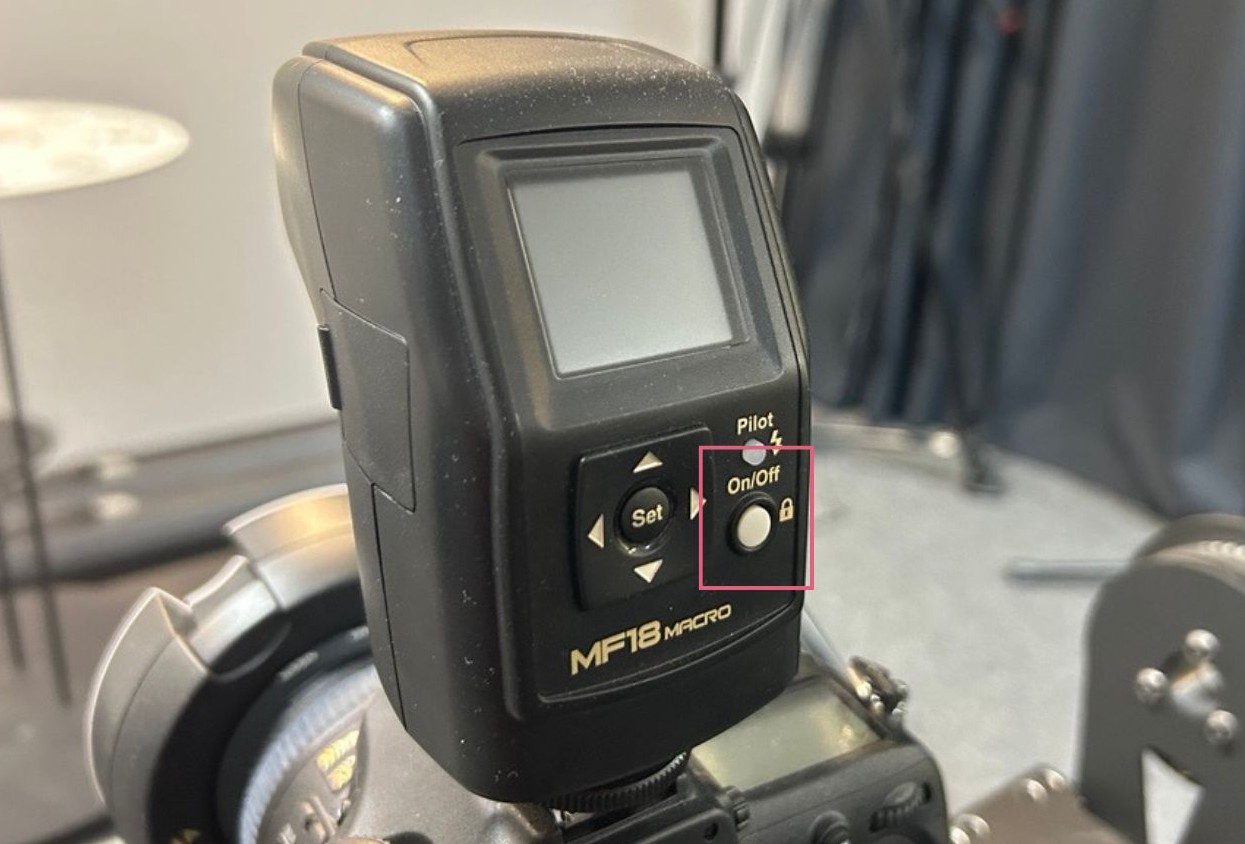
29. Check that the camera flash is still turned on as it can turn off automatically.

30. Click the start button on the top right of the screen and an orange start panel will come up. Click 'Play'.
The panel shows how many images it will take, how many have already been taken and the capture time estimation.
31. Check that the captures are being taken as you expect, and the flash is on.
ALWAYS WATCH THE FIRST CAPTURES INCASE SOMETHING HAS BEEN SET UP WRONG AND YOU NEED TO STOP THE RIG.
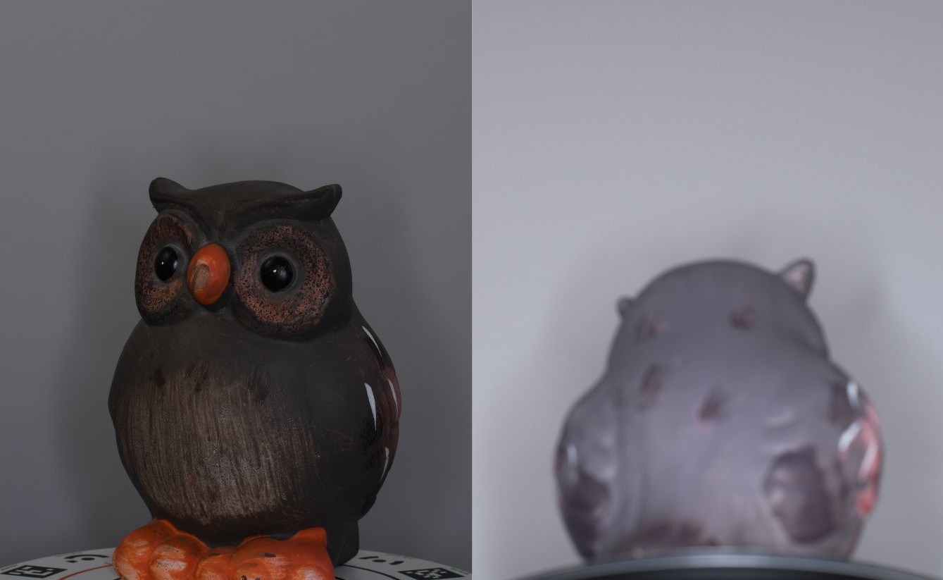
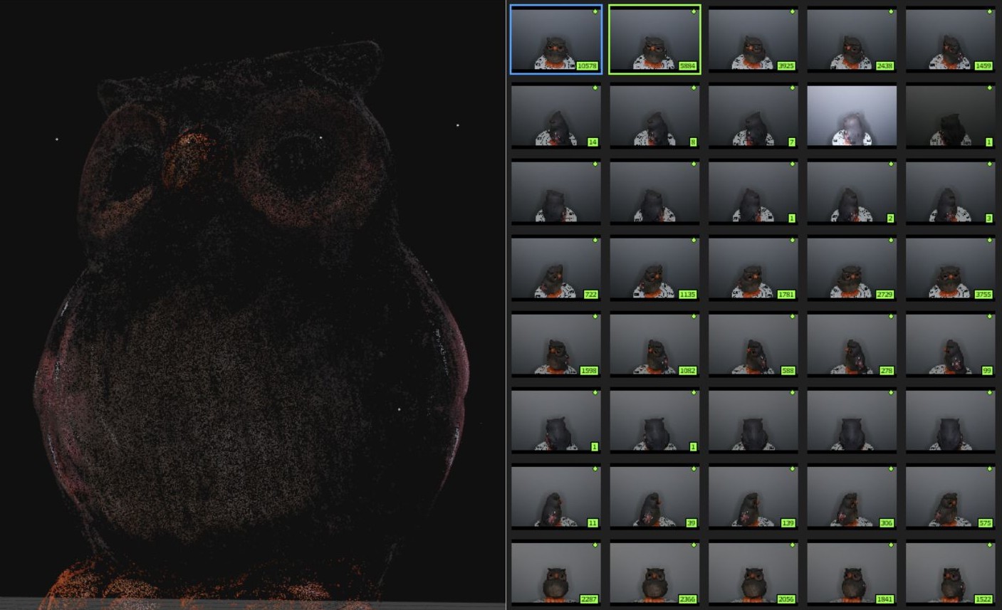
As the shots are taken, they will show green in the workspace. You can view the photos in the folder they are saved in.
The image on the left is suitable, whereas the image on the right is blurred and washed out.
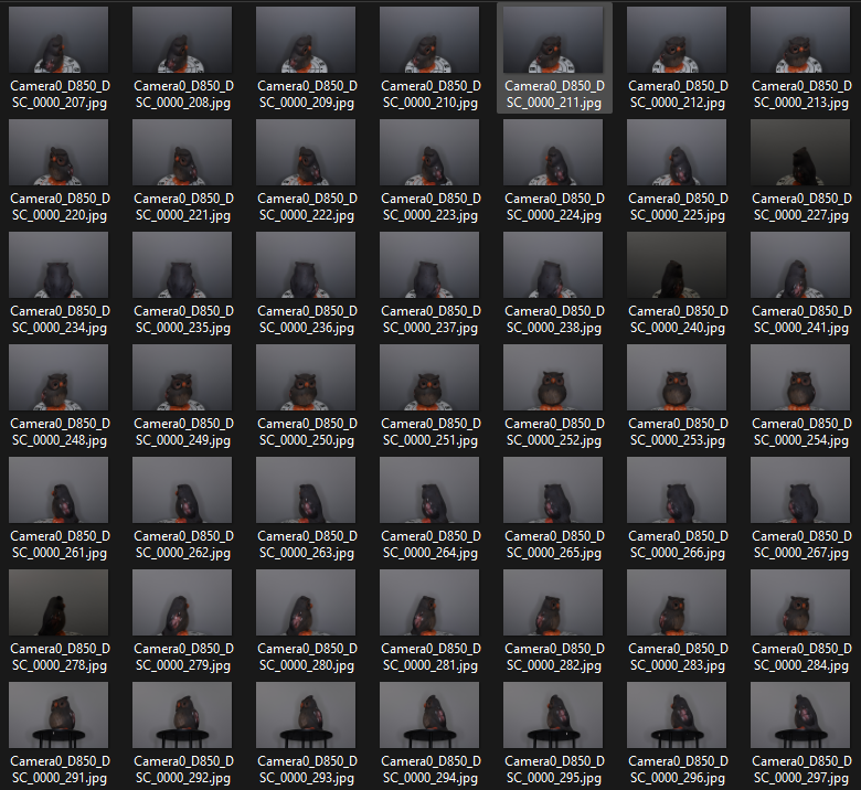
32. Go to your project folder and review the images before removing the object from the rig.
You may wish to shoot additional images, this can be done by reloading the capture sequence again, or, if there are problematic areas, these can be captured manually, by using live view to reframe the shot, focus, then capture.
Using your photos to create a 3D model in Reality Capture.
33. Open Reality Capture.

34. Add your imagery captured in Arago.
Do not import the capture of the pose camera calibration target.
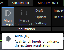
35. Click Align images, under the Alignment tab.
Align images can also be found under the Workflow, Process tab.
Reality Capture will give you a time estimation of when the alignment will complete.
36. You will be generated a point cloud. All photos that have been successfully aligned will show as green.
Do not worry if all of your images have not aligned, as long as a point cloud has been created.
At this point you can export the point cloud to edit in a different software if desired. You are not able to edit the point cloud in Reality Capture.

37. Create a 'Normal Detail' mesh, found under the Mesh Model tab.
You are able to generate a preview first if required to see if the point cloud data is sufficient to create a successful mesh.
The mesh produced will have no colour data.
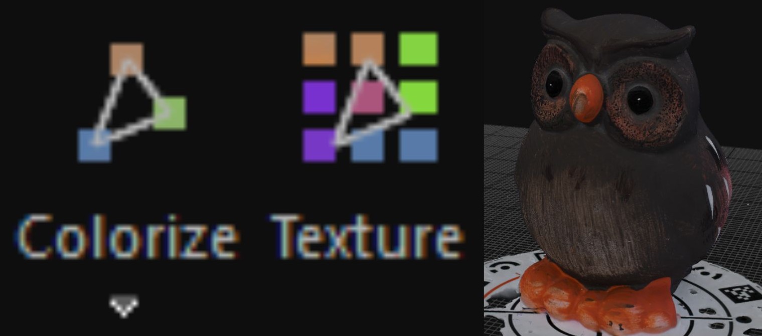
38. Colourize or texture the model, found under the Mesh Model tab.
Colourizing adds colour information to the vertices of the model, while texturing applies a 2D image (texture) to the surface.
Adding texturing will create a more realistic and detailed result, but a larger file.
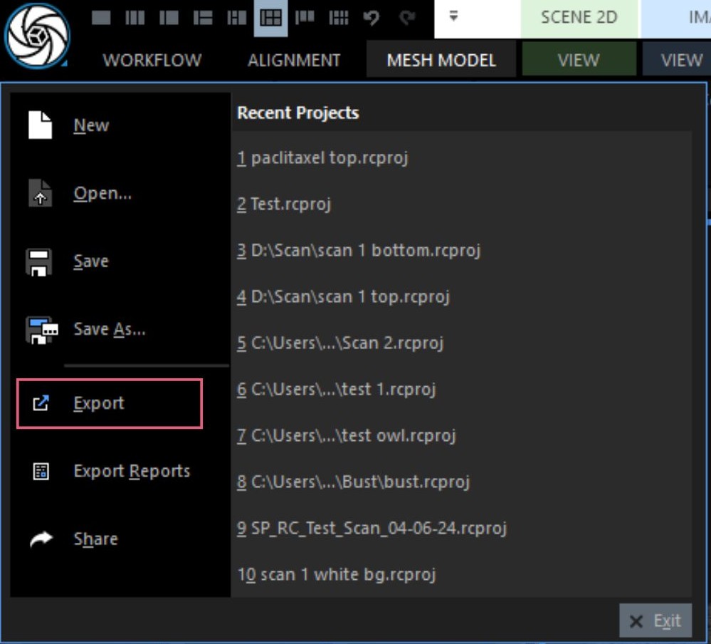
39. Export the model as an obj file.
Exporting the model as an obj file will also produce an mtl file, which must remain with the obj in order to preserve the colour data.
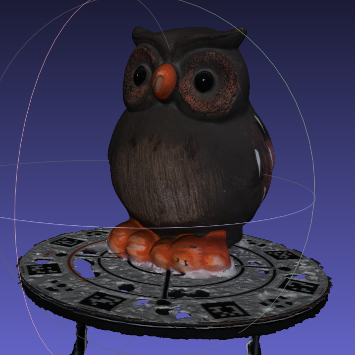
40. Open up the exported obj file and check the exported model is as expected.
You are able to open this file in a different 3D modelling software if you would like to edit the mesh. Detailed mesh editing is not supported in Reality Capture.