
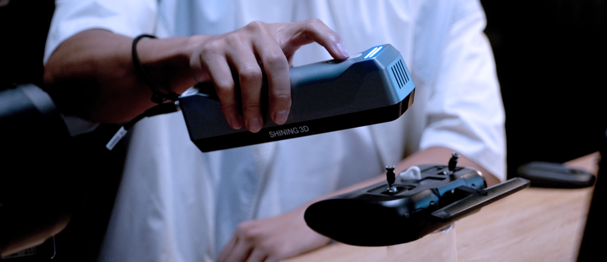
What is the EinStar?
The EinStar is a handheld structured light 3D scanner. The scanner is best used for medium to large sized objects (over 10cm^3). The scanner is very light weight and portable and is available on the uCreate loans system to take outside of the space.
This scanner supports coloured (textured) scans.
What could I use the EinStar for?
The EinStar is best for scanning medium to larger objects (over 10cm^3). If your object is small enough to fit on the EinScan-SP turntable, we recommend using this over than the EinStar.
It can also be used for scanning people. The EinScan H is available in the makerspace and can produce higher quality human scans but requires 2 people - the person being scanned and person doing the scanning. The EinStar can be used to take a scan of yourself.

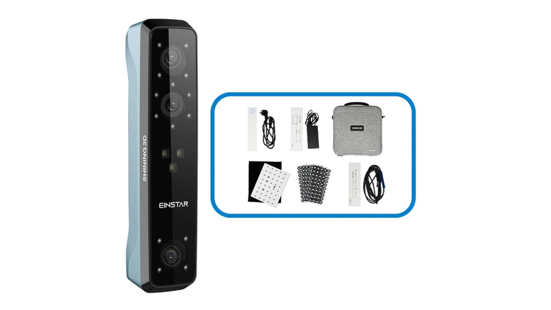
Where can I access the EinStar?
The EinStar is available on our loans system and can be taken outside of the makerspace.
When loaning it out you will be given a compact (roughly 30cm^3) case and a laptop.

Top Tips for scanning with the EinStar.

Adjusting brightness
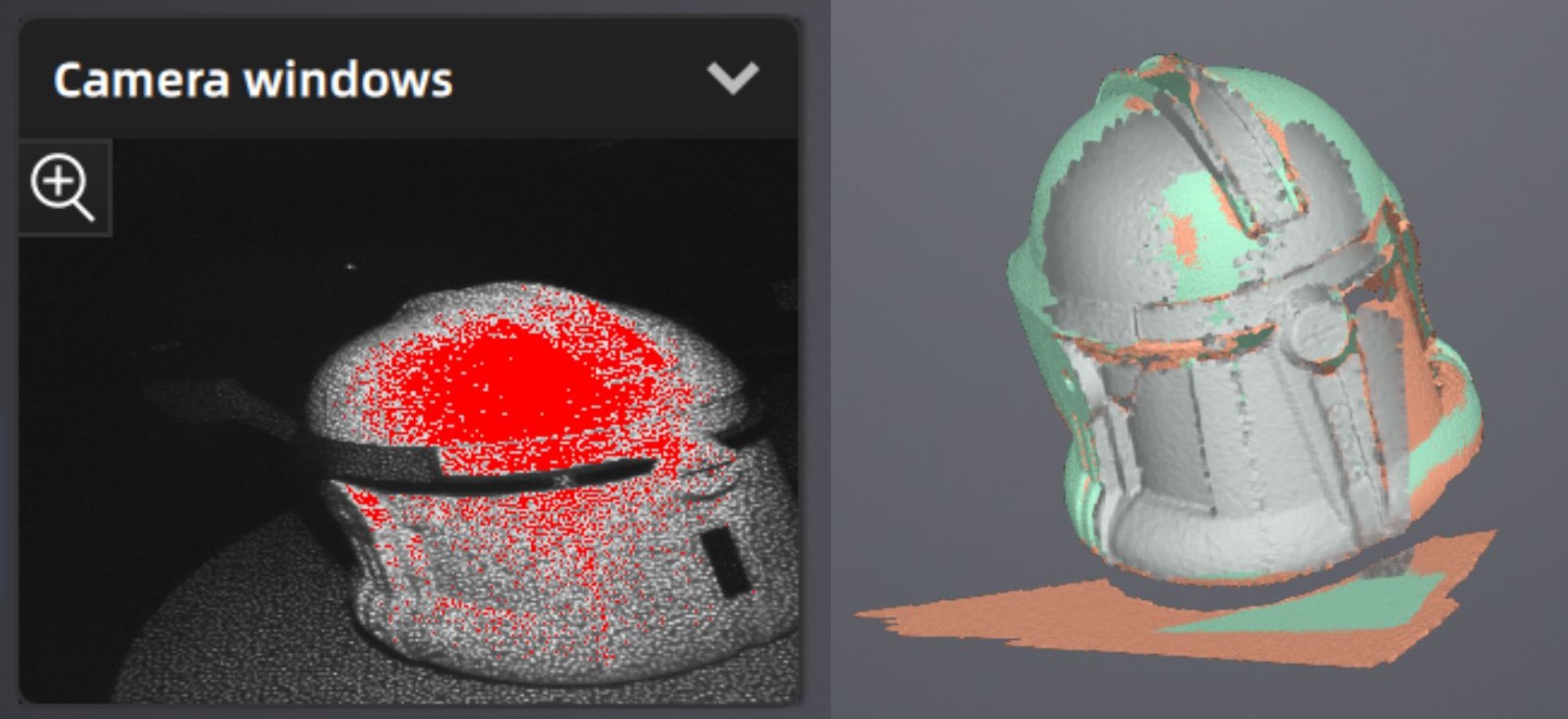
Before taking your scan, you will need to adjust the brightness for your object.
When setting the brightness for your scan, you are looking for some red to appear on the model in the viewing window. This means that the scanner can see the object.
It is helpful to go into preview mode and move the scanner over the object to check whether the brightness is correct.
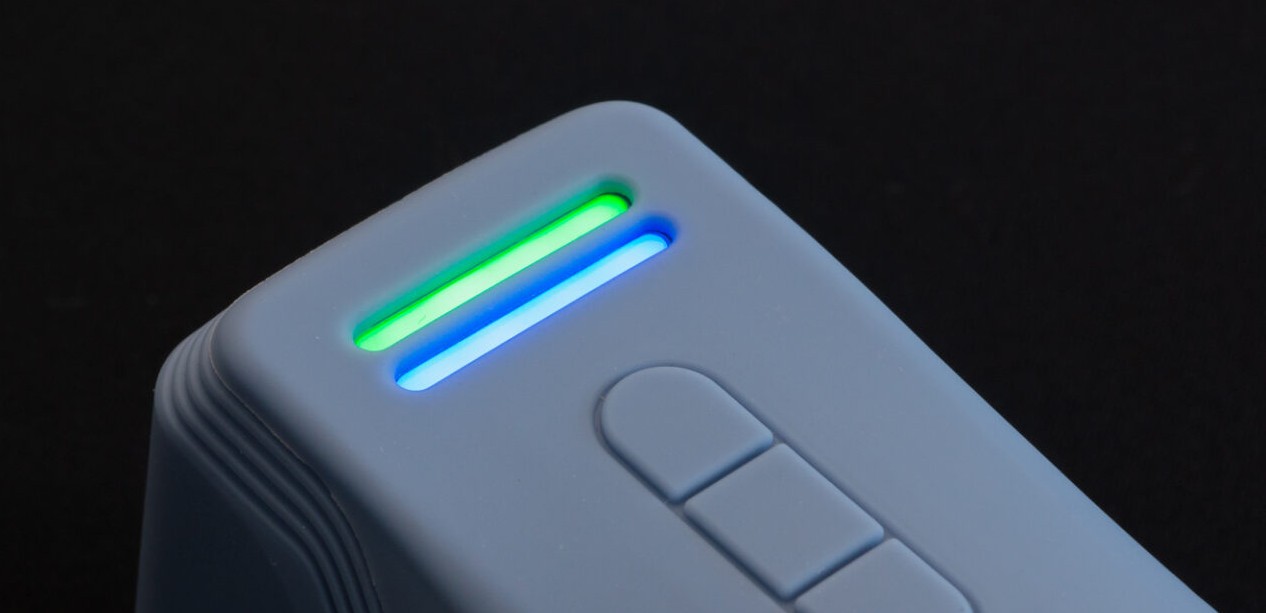
Scanning distance
The EinStar has an optimum scanning distance.
Use the light to stay in the green.
The top indicator is used to show the distance from the scanner to the object. Blue means the distance is too far, green is good, and red is too close. To capture maximum detail, you want to keep the indicator green as much as possible. The bottom LED indicator shows the status of the Einstar 3D scanner. Blue means everything is okay, whereas red signals a problem.
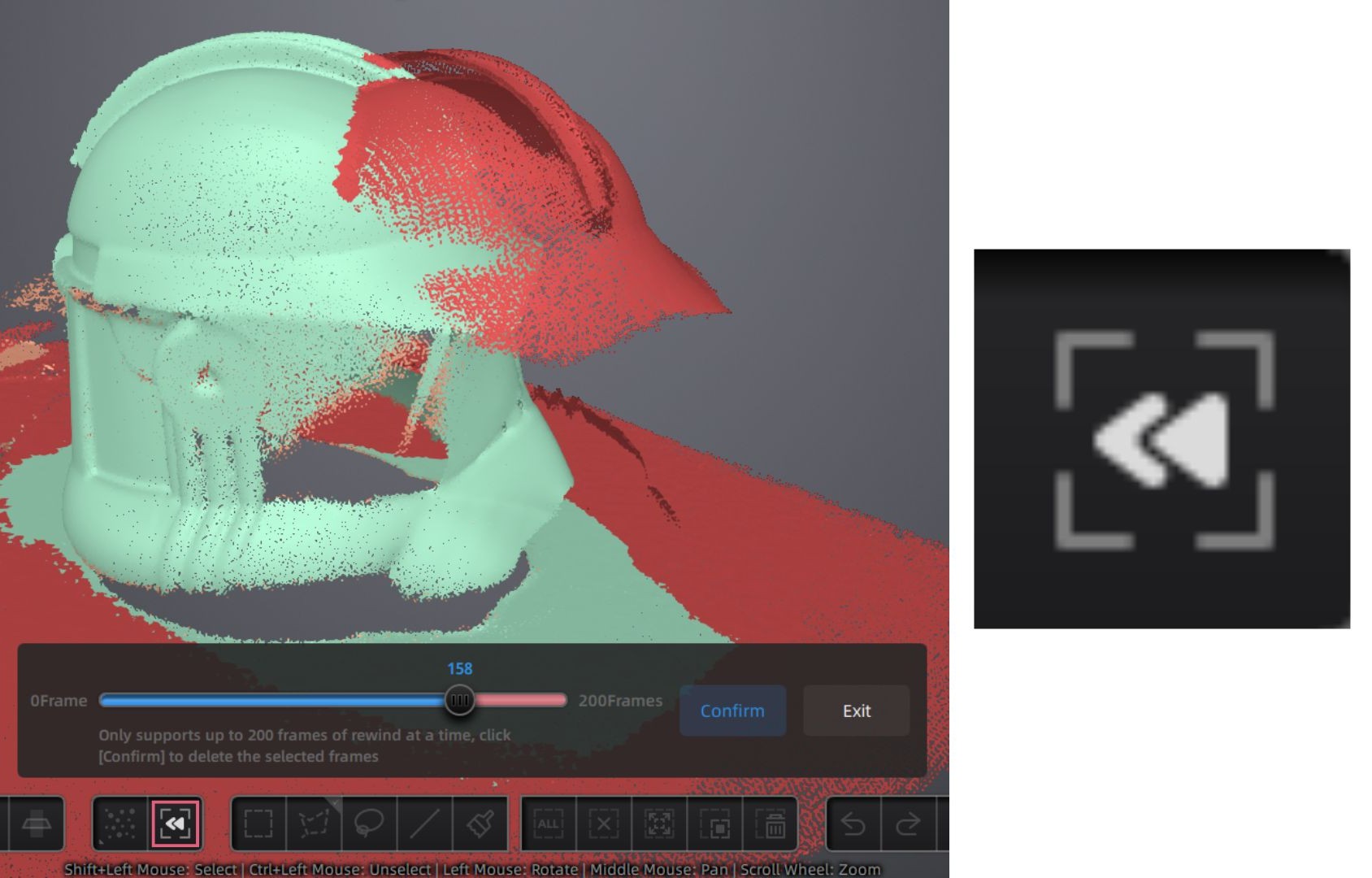
Rewind
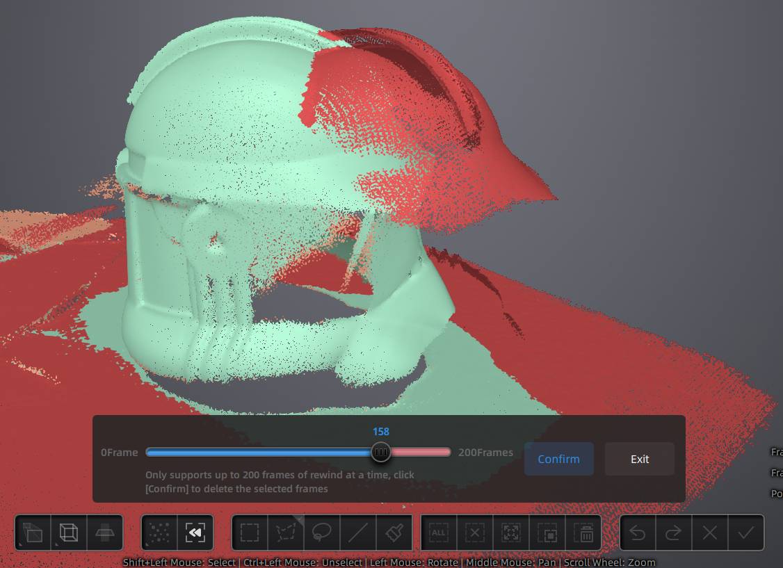
When taking multiple scans of the same object with the EinStar. The scanner will align the new scan with the previous scan. Sometimes this alignment is not correct.
Once you have paused scanning, you can rewind and delete specific frames, that may have not aligned correctly.
How to use the EinStar.
The software for the EinStar is very user friendly as walks you through the process of calibration and scanning.
For a written step-by-step of how to scan, see below.
Setting up the scanner and Calibration.
Calibration is required when there is a change in the lighting of the environment. You will likely need to calibrate the scanner when you first use it.
If you scan results are inconsistent, we suggest you also calibrate the scanner.

1. Start EXStar Application, with the scanner plugged in and turned on.
2. Create a project folder with the date and your name/student number in the folder ‘User Scans’ on the desktop.
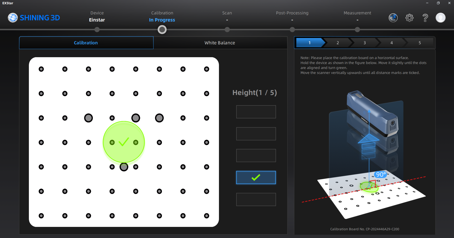
3. Click on calibration at the top of screen. Remove the calibration board from the velvet case and place on a table, making sure the orientation matches the graphic on screen. Follow the on screen instructions for calibration. You will be rotating the scanner and moving it up and down above the calibration board.

4. Calibrate white balance by following the onscreen instructions, using opposite side of board. You will be moving the scanner up and down above the calibration board.
Setting up for your scan.
To set up for your scan there are a variety of different settings depending on what you are scanning.
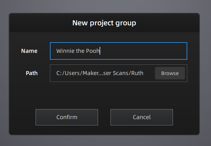
5. Create a new project and save into your premade folder.

6. Select the scan mode (human or object) and object size. If you are scanning an object, you must select whether it is small, medium or large.
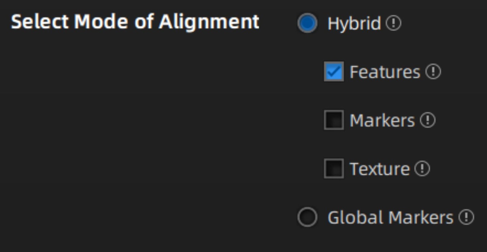
7. Select the mode of alignment from features, texture or markers. Features is best for objects with complex geometry, texture is best for objects with complex colour data and markers is best for objects with low geometry and colour data.
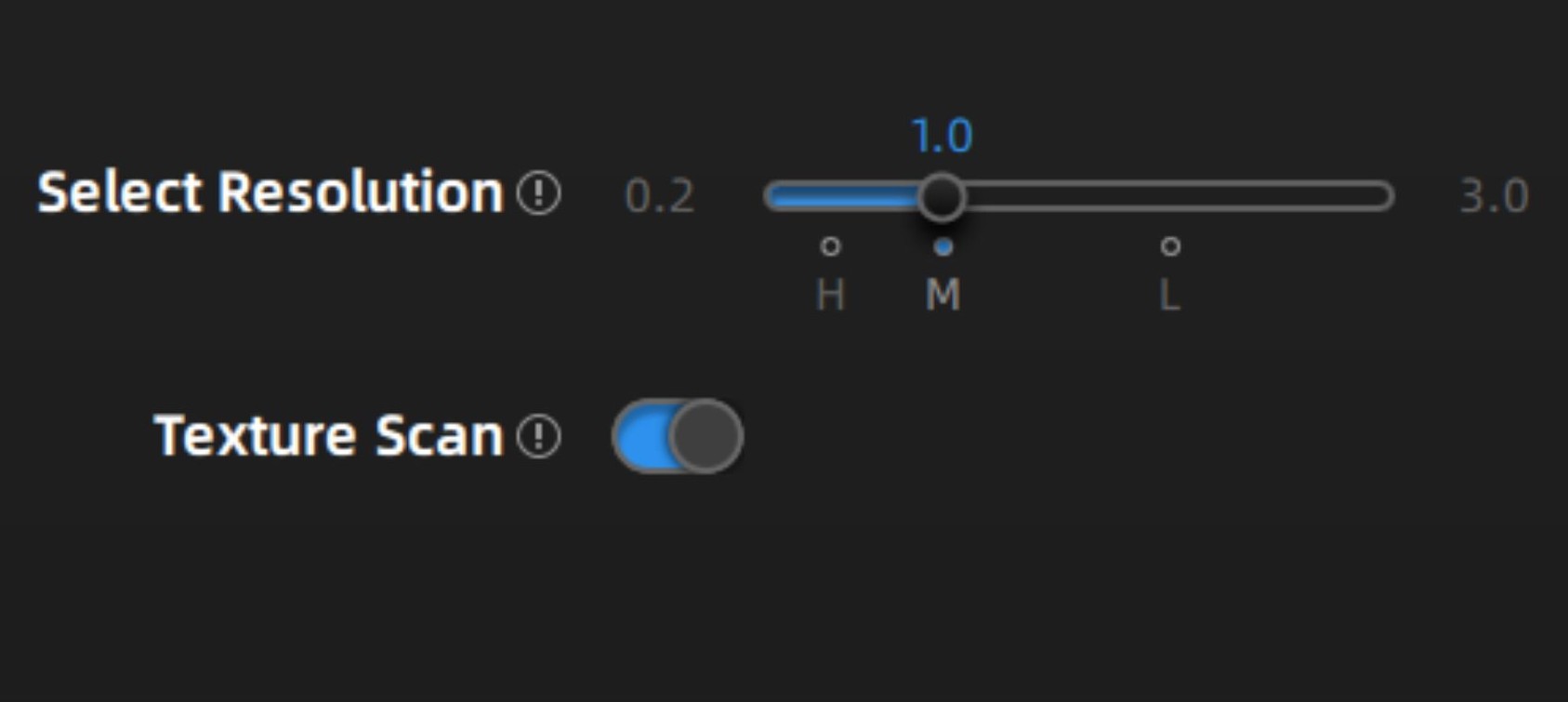
8. Select the resolution and if you want a texture (colour) scan. For most objects, we recommend medium detail. The higher the detail, the more likely the scanner is to lose tracking during scanning.
Scanning and cleaning up your scan.
To set up your scan there are a variety of different settings to adjust in order to get the best result.
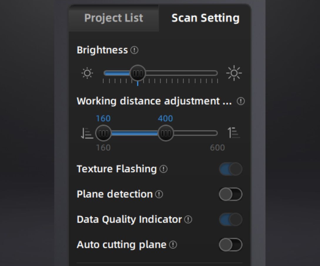
9. Adjust the brightness, set your working distance, texture flashing and data quality indicator. It can be helpful to enter preview mode by pressing play when adjusting the brightness, see top tips above for more information about setting brightness. The working distance is how far away you are from the object you are scanning. Texture flashing gives higher quality colour scans. The data quality indicator helps to monitor your scanning distance and should always be turned on.
10. Click start scan and slowly move over the object to scan. If the scanner loses tracking, return to the last place that the scanner had tracking. Click the play button again to pause the scan.
11. You can clean up your scan using rewind (see top tips) and cutting out the surface that your object is placed upon.
12. You may need to take multiple scans. Never move the object while you are scanning. With the scan paused, reorientate the object and press start scan again. The new scan will overlays onto the existing scan data.
Meshing your model.
If you are looking to make an STL file from your 3D scan, the easier way is to mesh it inside the EXStar software.
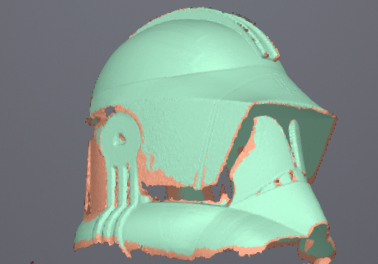
Meshing is the process of drawing polygons between all of the points captured by the scanner to create a model.

13. Click optimizing and generating point clouds.
14. Click mesh model to open the meshing window.
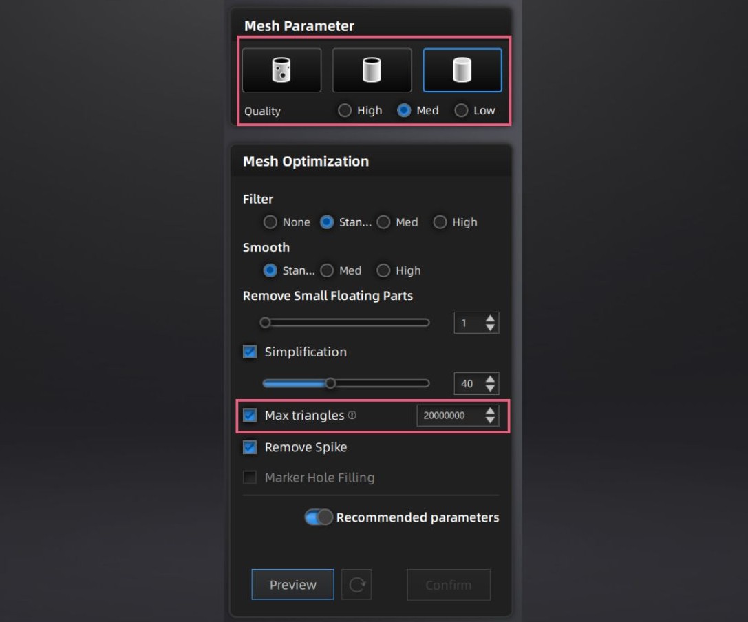
15. Select watertight, semi-watertight or unwatertight (for 3D printing, your model must be watertight). Select your quality level, we recommend medium and set your maximum number of triangles. We recommend to have your maximum number of triangles set to 300,000. This will make a file less than 25MB and can be open in TinkerCAD.
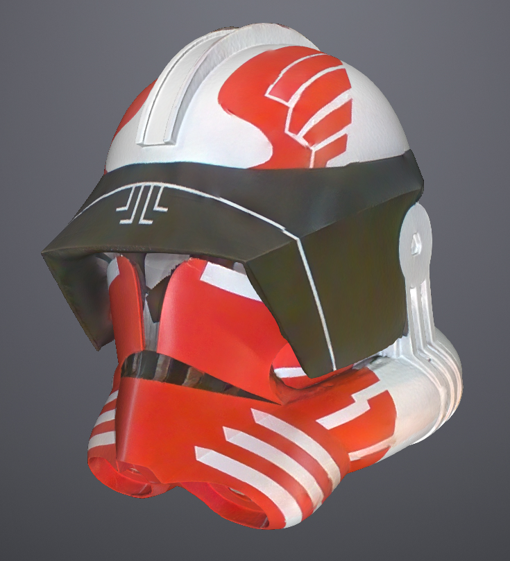
16. Click preview to view the result. The software will now generate your model, this may take a few minutes. If you are not happy with the result, you can go back and adjust your parameters. Click confirm when you are happy with your mesh.
Post-processing of your mesh and saving your scans.
After meshing your model, you are still able to make small alterations, as well as saving your final product.
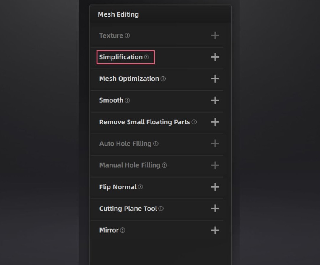
17. If you want to reduce your file size, you can simplify your model by reducing the number of polygons.
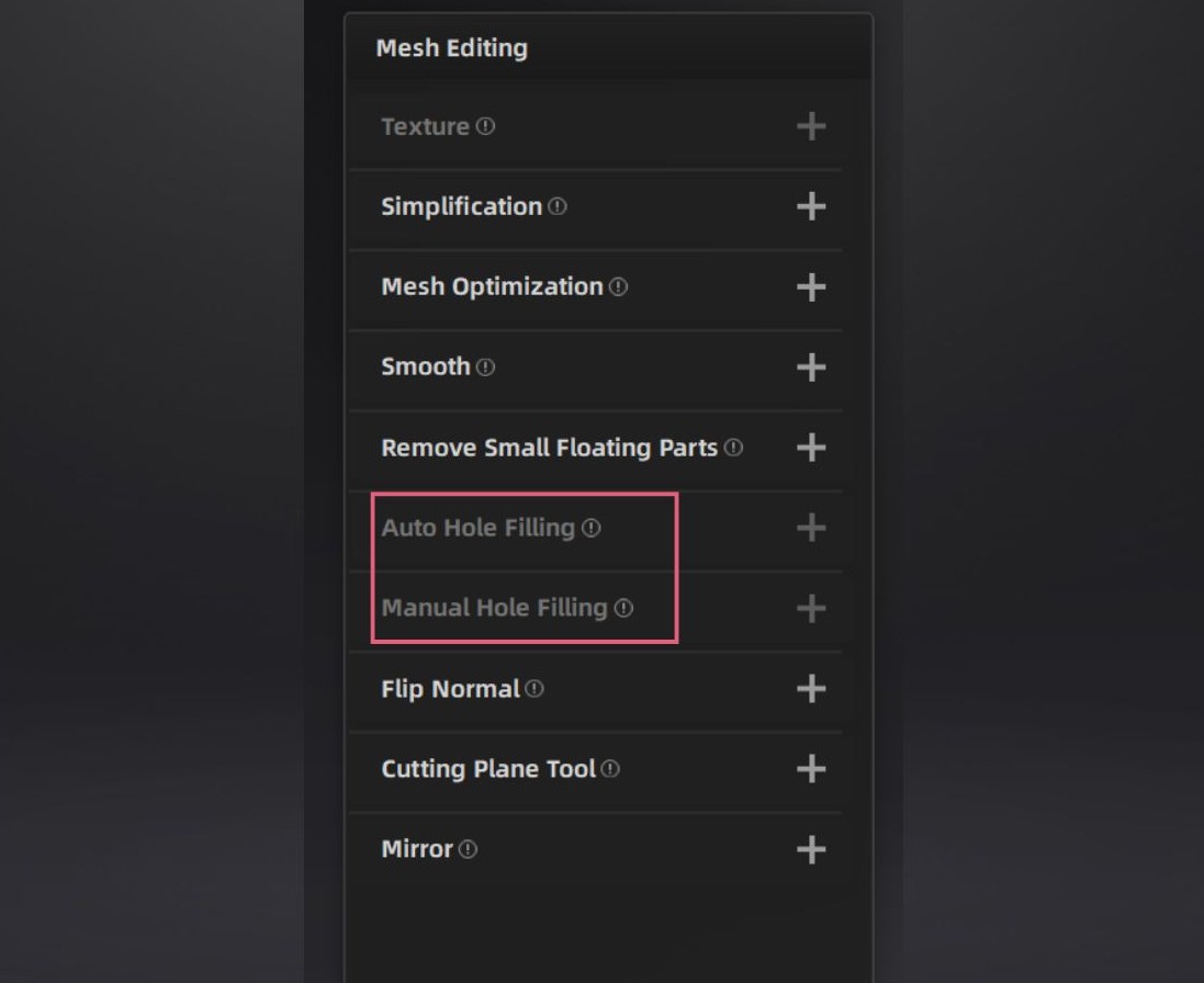
18. If you selected unwatertight model during the meshing process, you can retrospectively fill in holes in your mesh. This can be helpful if you only want some of the holes filled. Hole filling will be greyed out if you chose a watertight mesh.
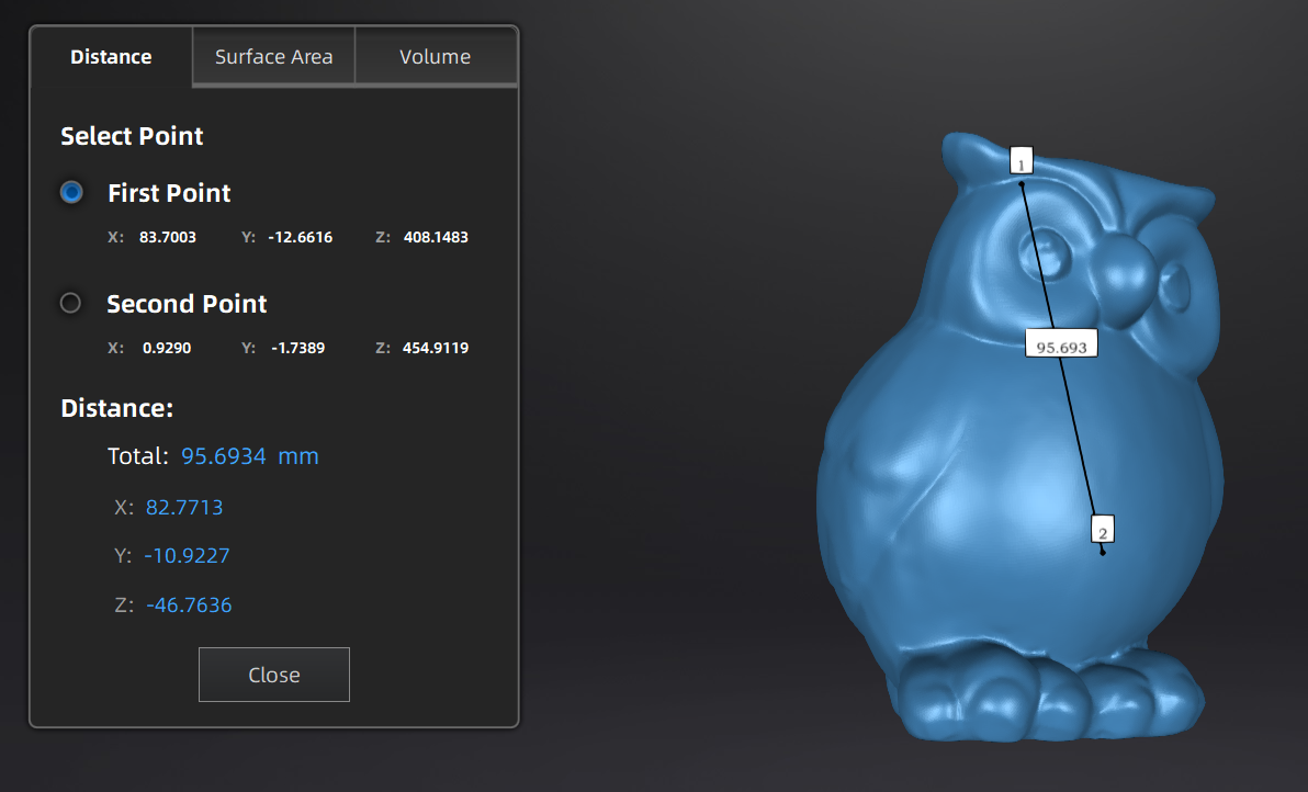
19. On measurement panel, click measurement tool. Select two points to see distance between them. You can also see the surface area and volume. Useful to take measurements you wouldn’t be able to on the physical object.

20. To start saving your project, click Export the scan. Select to save the mesh locally. Select file types asc (whole scan), stl (form data) and obj (form and colour data). When saving as an obj file, a jpg file will also be generated. This must remain with the obj file to preserve the colour data.